Sequences of operations for high thermal mass radiant systems
1. Summary
The intent of these sequences of operation is to use slowly adjusted slab temperature setpoints to control radiant system operation to maintain comfort in the zone. The strategy operates based on a slab temperature measurement and uses information from the zone temperature during the occupied period to make minor adjustments to the slab setpoint for the next day. The strategy constrains the radiant system to take advantage of thermal inertia and condition the slab only during certain periods of time. For a given project, this allows designers to select for either: more efficient and cost effective operating hours (e.g. system only operates at night), longer operating hours to yield smaller heating or cooling plant sizes (e.g. system sized assuming 18 or 24 hour operation on the design day), or aim to provide a more uniform daily range of comfort conditions (e.g., time pre-cooling such that it approximately accounts for the slab time constant and the peak loads).
2. Scope
These sequences apply to zones with a high performance envelope design that use high thermal mass radiant systems for both heating and cooling, and have reasonably uniform internal loads.
Additional information
These sequences do not apply to radiant metal ceiling panels, which have a faster response and can be controlled similarly to all-air systems. The sequences also do not apply where heat exhange between the ceiling and floor surfaces are substantially blocked (e.g., by a wall to wall drop ceiling), and/or where the ceiling surface is lightweight (e.g. the uppermost floor in a building which uses metal deck without concrete for the roof).
More formally, these sequences apply to cases where:
a) The response time for the radiant system in response to a step change in flow is greater than approximately 5 hours. See this paper for more detail. Faster responding systems (e.g. a VAV box, or a radiant metal ceiling panel) should not be controlled using these sequences.
b) The zone has a high performance envelope with limited direct solar. This minimizes the disturbance due to changing outside conditions. This is the case for typical radiant designs in most climates, even those with significant inter-day temperature changes, as the change in heat gain/loss to the exterior is relatively small compared to internal gains and heat stored in the mass of the zone.
c) The zone has reasonably uniform internal loads from day to day, such as an office environment. Zones with highly fluctuating and irregular schedules (e.g. an event space) should not be controlled using these sequences.
3. Pre-requisites
3.1 The (adjustable) upper (T_comf_upper_limit) and lower (T_comf_lower_limit) operative temperature limits for comfort shall be calculated based on ASHRAE Standard 55. Suggested values for typical office applications are 78 °F and 70 °F respectively. The minimum range between the upper and lower limits shall be constrained to be 5 °F.
Additional information
The official ASHRAE Standard 55 web tool for performing the above calculations can be found at comfort.cbe.berkeley.edu.
3.2 T_offset shall be defined as a safety factor to the comfort temperature limit, typically 1.0 °F, and adjustable up to a maximum value of 1/3 of the range between T_comf_upper_limit and T_comf_lower_limit.
3.3 The zone air temperature sensor (T_air) shall be assumed to represent operative temperature (i.e., assuming that mean radiant temperature and air temperature are equal) unless an operative or globe sensor is present in the zone.
3.4 Where multiple air temperature sensors are located within a large radiant zone, the median (or mean if median is not feasible) value of all of these sensors shall be used for the purposes of radiant slab temperature reset. Functionality shall be provided to the operator to exclude any specific temperature sensor(s) from the mean/median calculation as needed.
3.5 A temperature sensor shall be installed in the concrete floor slab, described throughout as a 'slab temperature sensor', or T_slab, located:
3.5.1 equidistant between two adjacent rows of PEX tubing;
3.5.2 at the same depth in the slab as the PEX tubing;
3.5.3 as close to halfway (as is feasible given the geometry and constraints involved) along the length of the PEX tubing from the manifold, on the tubing loop that covers the floor area nearest the geometric center of the zone floor area.
3.6 The slab temperature setpoint shall be defined as T_slab_stpt. At first system startup, T_slab_stpt shall be initialized at T_comf_lower_limit. Values for T_slab_stpt shall be limited to between 80 °F and 65 °F (both adjustable).
3.7 Where multiple slab temperature sensors are located within a large radiant zone, the median value (or mean if median is not feasible) of all of these sensors shall be used for the purposes of radiant slab control. Functionality shall be provided to the operator to exclude any specific temperature sensor(s) from the median/mean calculation as needed.
3.8 A radiant water temperature control zone is defined as a single radiant zone, or group of radiant zones, in which the supply water temperature is directly controlled. An immersion temperature sensor shall be installed downstream of the control point supplying heated (T_water_htg) and cooled water (T_water_clg) to each radiant water temperature control zone.
Additional information
§ For example, for a radiant system where the changeover between heating and cooling occurs at the plant level for the whole building, and there are no mixing valves, T_water_htg and T_water_clg could be the leaving boiler and leaving chiller temperatures respectively.
§ For example, for a radiant system where a mixing valve supplies a single, or multiple radiant zones, T_water_htg and T_water_clg is the temperature downstream of that mixing valve.
3.9 A start hour (O_start) and end hour (O_end) shall be clearly defined to represent the period of the day in which the zone is occupied, described throughout as the occupied period. The aim of the sequences is to maintain zone conditions within the upper and lower limits described in §3.1 during this period.
3.10 The maximum and minimum indoor air temperature (T_air_daily_max and T_air_daily_min respectively) shall be calculated over the entire occupied period for the zone once per day, at the end of the occupied period (O_end). Depending on the heating and cooling plant
Additional information
§ Where §3.6 applies, the median calculation occurs every sampling instance (e.g. every minute). The minimum and maximum calculation shall be performed on these median values at the end of the occupied period.
§ If within the capabilities of the automation system programming language, the 90th and 10th percentile values are preferable to the maximum and minimum to avoid outlier measurements.
3.11 A start hour (L_start) and end hour (L_end) of the lockout period shall be clearly defined to represent the period of the day in which the radiant system cannot operate, described throughout as the lockout period. At all other times, described throughout as the available period, the radiant system is available to operate if a cooling or heating call occurs. This allows the designer or operator to take advantage of the thermal inertia of the system as desired. Separate lockout periods for heating and cooling mode shall be provided.
Additional information
§ To prioritize nighttime pre-cooling, more efficient cooling plant conditions, lower electricity energy costs, and reduced electricity demand charges, the radiant system should be locked out during the occupied period, so that it operates during the night.
§ To prioritize uniform comfort conditions within the zone, the radiant system should be locked out for a period approximately 12-16 hours long, starting 3-5 hours before the end of the occupied period.
§ To reduce the size of the cooling or heat plant, the radiant system should be not be locked out, so that the total cooling and heating loads are distributed across the entire 24 hour period. An alternate to this is to locked out the radiant system for only the hours that correspond with peak demand and energy charges (e.g. 3p.m. to 8p.m.), which combines the benefit of avoiding peak pricing while still significantly reduced plant size.
§ This online design tool provides a rapid, simplified method for approximately evaluating the above design points. The exact design can be more accurately estimated using a simulation tool that implements the ASHRAE Heat Balance method and supports radiant systems.
§ Note that it is often advantageous (from an efficiency or utility tarif perspective) to have separate lockout periods for heating and cooling mode, depending on the heating and cooling system serving the radiant system. For example for an air-source heat pump, cooling during the night is most efficient, while heating during the middle of the day is more efficient, and the lockout schedules (independent for heating and cooling) should reflect this.
3.12 The lockout period for each zone shall be staggered across the whole building. For example, each zone lockout period shall vary by 1 minute across a window of 30 minutes.
Additional information
§ This avoids synchronous pulsing of valves (due to the pulsed flow control described later), mitigates issues with differential pressure control of pumps, and reduces startup loads on the heating/cooling plant when the lockout period ends.
3.13 The daily running mean of the outdoor air temperature (T_out_running_mean) shall be calculated (e.g. according to EN 15251, T_out_running_mean for the current day is equal to 0.8 times the T_out_running_mean for the previous day plus 0.2 times the daily average of the outdoor air temperature from the previous day).
4. Radiant zone mode
4.1 On system first startup, zone mode shall be determined at the end of the occupied period by the following (in sequence):
4.1.1 If T_air_daily_max was greater than T_comf_upper_limit - T_offset during occupied hours, enter cooling mode.
4.1.2 If the condition in 4.1.1 was not met, and T_air_daily_min was less than T_comf_lower_limit + T_offset during occupied hours, enter heating mode.
4.2 The zone shall switch into cooling mode only if there have been no heating calls within the last 24 hours (adjustable upwards only, minimum value 24 hours), and T_air_daily_max was greater than T_comf_upper_limit - T_offset during occupied hours within the last 24 hours.
4.3 The zone shall switch into heating mode only if there have been no cooling calls within the last 24 hours, and T_air_daily_min was less than T_comf_lower_limit + T_offset during occupied hours within the last 24 hours.
4.4 Heating mode shall be locked out when the average outside air temperature in the last 24 hours is above 65 °F (adjustable).
Additional information
§ For a high thermal mass system designed as the primary source of heating and cooling there will be a significant number of days per year in which the average 24 hr load is small enough that the thermal inertia of the system alone causes conditions to remain within the comfort limits. Primary heating or cooling is not required on these days. The above sequences prevent the system from providing heating and cooling to the slab during the same day and also ensures that there is at least one full day in which the slab does not operate (i.e., drifts) between mode changeovers.
5. Radiant heating & cooling calls:
5.1 For each flow control zone, control the water flow rate to the radiant slab according to the following.
5.2 Preferred option: Pulsed flow control method
Additional information
§ Compared to on/off control, pulsed flow control will have lower overall pumping power and higher average return water delta temperature.
§ More detail can be found in this this more detailed paper.
§ Pulsed flow control where the (constant) open pulse duration is approximately the time required to 'flush' the tubing loop at design flow will yield a similar cooling/heating capacity to average flow relationship as idealized variable flow control (i.e., using a proportional/modulating valve). However, controllability at low part loads (i.e., ultra low flow rates) is much better for pulsed flow control than for variable flow control, and initial costs are lower.
§ The designer can calculate the flush time for their specific case using design flow rate, diameter, and length. However, capacity is not highly sensitive within the range of variation in 'flush' time for typical radiant system designs (3-7 minutes). 4 minutes is a reasonable default value.
5.2.1 The slab shall respond to a cooling or heating call by pulse width modulating the valve open and closed. The open pulse duration shall be fixed and the closed pulse duration varies.
5.2.2 The duration of the open pulse (P_open) shall be 5 minutes (adjustable from 3 to 15 minutes).
5.2.3 The duration of the closed pulse (P_closed) shall be determined by the output of a control loop described below. The maximum duration of the closed pulse (P_closed_max) shall be 120 minutes (adjustable from 60 to 240 minutes).
5.2.4 Cooling calls:
i. A call for cooling shall occur at the start of the available period (i.e. immediately after the end of the lockout period, L_end), when all of the following conditions are met:
a. the slab temperature (T_slab) is greater than the slab setpoint (T_slab_ stpt); and
b. the zone is in cooling mode; and
c. the supply water temperature (T_water_clg) is 2 °F or more below the slab temperature (T_slab).
ii. At the end of the lockout period, a proportional control loop shall be used to control the pulse rate. The loop percentage (Clg_loop_out) shall be calculated as the error between the slab temperature and the setpoint divided by the proportional band according to Clg_loop_out = (T_slab - T_slab_stpt)/PB where PB is the proportional band (typically 2 °F, adjustable). The duration of the closed pulse shall be determined based on the output of the above proportional control loop according to P_closed = P_closed_max * (1 - Clg_loop_out).
5.2.5 Heating calls:
i. A call for heating shall occur at the start of the available period (i.e. immediately after the end of the lockout period, L_end), when all of the following conditions are met:
a. the slab temperature (T_slab) is less than the slab setpoint (T_slab_ stpt); and
b. the zone is in heating mode; and
c. the heating supply water temperature (T_water_htg) is 2 °F or more above the slab temperature (T_slab).
ii. At the end of the lockout period, a proportional control loop shall be used to control the pulse rate. The loop percentage (Htg_loop_out) shall be calculated as the error between the slab and the setpoint divided by the proportional band according to Htg_loop_out = (T_slab_ stpt - T_slab)/PB where PB is the proportional band (typically 2 °F, adjustable).The duration of the closed pulse shall be determined based on the output of the above proportional control loop according to P_closed = P_closed_max * (1 - Htg_loop_out).
5.2.6 Values for Clg_loop_out and Htg_loop_out shall be limited to within the range of 0% to 100% at all times.
5.2.7 If P_closed is calculated to be less than P_open, P_closed shall be overwritten to 0 and the valves shall remain open continuously.
5.2.8 Values for Clg_loop_out, Htg_loop_out, P_open and P_closed shall be calculated once per P_closed_max period, starting at the beginning of the available period (i.e. immediately after the end of the lockout period, L_end).
5.3 Alternative option: On/off control
5.3.1 The slab shall respond to a cooling or heating call by opening or closing the valve.
5.3.2 Cooling calls:
iii. A call for cooling shall occur at the start of the available period (i.e. immediately after the end of the lockout period, L_end), when all of the following conditions are met:
d. the slab temperature (T_slab) is greater than the slab setpoint (T_slab_ stpt); and
e. the zone is in cooling mode; and
f. the supply water temperature (T_water_clg) is 2 °F or more below the slab temperature (T_slab).
iv. At the end of the lockout period, a on/off control loop shall be used to control the valve based on the slab setpoint (T_slab_stpt).
5.3.3 Heating calls:
iii. A call for heating shall occur at the start of the available period (i.e. immediately after the end of the lockout period, L_end), when all of the following conditions are met:
a. the slab temperature (T_slab) is less than the slab setpoint (T_slab_ stpt); and
b. the zone is in heating mode; and
c. the heating supply water temperature (T_water_htg) is 2 °F or more above the slab temperature (T_slab).
iv. At the end of the lockout period, a on/off control loop shall be used to control the valve based on the slab setpoint (T_slab_stpt).
5.4 An active heating or cooling call shall terminate and the valve(s) shall close upon entering the lockout period (L_start) each day.
5.5 An active heating call shall terminate, and the valve(s) shall immediately close, if T_slab is above the upper limit defined in §3.6. An active cooling call shall terminate, and the valve(s) shall immediately close, if T_slab is below the lower limit defined in §3.6.
5.6 An active heating call shall terminate, and the valve(s) shall immediately close, if T_slab is above T_water_htg. An active cooling call shall terminate, and the valve(s) shall immediately close, if T_slab is below T_water_clg respectively.
Additional information
This requirement prevents uneccessary pumping power if the supply water temperature is close to the slab temperature.
6. Radiant zone valve control
6.1 For a 4-pipe system:
6.1.1 The system shall respond to a call for cooling or heating by isolating the heated and cooled water system, and opening valves to provide cooling or heating, respectively.
6.2 For a 2-pipe system:
6.2.1 If the changeover piping system is in cooling mode:
i. Respond to a call for cooling by opening the valve(s) to provide flow through the radiant system
ii. Respond to a call for heating by creating a heating changeover request to the changeover system.
6.2.2 If the changeover piping system is in heating mode:
i. Respond to a call for heating by opening the valve(s) provide flow through the radiant system.
ii. Respond to a call for cooling by creating a cooling changeover request to the changeover system.
7. Radiant slab temperature setpoint reset
7.1 Preferred option: Control based on feedback from previous day
7.1.1 A new slab setpoint shall be calculated once per day, at the end of the occupied period (O_end), based on the zone air temperature during that occupied period.
7.1.2 The zone temperature error for that occupied period (E) shall be calculated:
7.1.2.1 When (i) a cooling or heating call occurred during the last available period (i.e. the zone actually required heating or cooling) and (ii) the valve was closed at least once during the last available period (i.e. the radiant system was not operating at capacity), the error shall be determined as:
7.1.2.1.1
For cooling mode:
E=(T_comf_upper_limit -T_offset) - T_air_daily_max.
7.1.2.1.2
For heating mode:
E= (T_comf_lower_limit + T_offset) - T_air_daily_min.
7.1.2.2 Otherwise the error shall be determined as: E= 0.
7.1.3 The slab temperature setpoint (T_slab_stpt) for the following day shall be modified to T_slab_ stpt + E * K, where K, a proportional gain, is typically 0.5, adjustable from 0.2 to 1.
7.1.4 Slab temperature reset shall not operate during an extended unoccupied period of 24 hours or more (i.e. the weekend). During this time period T_slab_stpt will remain at it's previous value each day.
Additional information
This paper describes an early version of the slab temperature setpoint reset strategy in more detail, along with simulation data showing the effect on the results.
7.2 Alternate option: Outside weather based control
7.2.1 Slab temperature setpoint (T_slab_stpt) shall be reset once per day, linearly based on a daily running mean outside air temperature.
Additional information
Note that the outside weather based control option allows for significant simplification of the sequences. Aside from the slab temperature setpoint, potentially, the radiant zone mode can also be determined solely based on the outside air temperature. However, both of these solutions will likely require manual tuning after the building has been operating, which may be difficult to ensure in practice.
8. Optional: Supplementary cooling and heating systems serving the same radiant zone
8.1 Supplementary cooling and heating systems in the zone with a faster response time than the radiant system such as VAV boxes, chilled beams, radiant ceiling panels, etc. shall be controlled as per ASHRAE Guideline 36 using T_comf_lower_limit and T_comf_upper_limit as their heating and cooling setpoints, respectively (i.e., without the offset, T_offset).
Additional information
§ Excluding the offset ensures that the supplementary heating and cooling system is secondary to the radiant system. These secondary systems should operate to maintain comfort in the zone when either average daily zone loads or short term peaks in zone load exceed the capacity of the radiant system to handle or respond to.
8.2 All sequences associated with the supplementary system shall operate independently from the radiant sequences described in this document.
8.3 Additional logic required for slab temperature reset logic based on zone temperature feedback (see §7) when a supplementary heating or cooling system is present:
8.3.1 When a supplementary cooling system is present: if the supplementary cooling system activated on the previous day, and T_air_daily_min was below T_comf_lower_limit, override the calculated value of E to + T_offset.
Additional information
§ This prevents the slab reset from from continually decreasing the slab setpoint, causing overcooling.
8.3.2 When a supplementary heating system is present: if the supplementary heating system activated on the previous day and T_air_daily_max was above T_comf_upper_limit, override the calculated value of E to - T_offset.
Additional information
§ This prevents the slab reset from from continually increasing the slab setpoint, causing overheating.
9. Optional: Radiant water temperature setpoint reset
9.1 For each water temperature control zone, reset the heating and cooling water temperature setpoint according to the following.
Additional information
A water temperature control zone can serve:
a) an individual thermal
zone (i.e., a single large room);
b) a group of thermal zones where the loads are likely to be similar and/or
which are closely thermally coupled to each other (e.g. three water temperature
control zones each encompassing all thermal zones on all floors for South,
North, and Interior respectively);
c) all thermal zones in the building (e.g. the leaving temperature from the
heating/cooling plant) where the expected variation between loads within the
building is low.
9.2 Option 1: Request based control
9.2.1 The system shall generate a heating or cooling water temperature request if:
9.2.1.1 For pulsed flow control option: Htg_loop_out or Clg_loop_out is greater than 80% (adjustable) and a heating or cooling call occurred within the last 24 hours respectively.
9.2.1.2 For on/off control option: The valve is o 80% (adjustable) and a heating or cooling call occurred within the last 24 hours respectively.
9.2.2 Water temperature setpoints shall respond to temperature requests using trim and respond logic (see ASHRAE Guideline 36 for more detail) with a timestep of 72 hours and the following parameters (adjustable)
9.2.2.1 For cooling: SPtrim: 0.3 °F, SPres: -0.6 °F, SPres-max: -0.9 °F, and other values (min, max, etc) chosen based on design.
9.2.2.2 For heating: SPtrim: -0.3 °F, SPres: 0.6 °F, SPres-max: 0.9 °F, and other values (min, max, etc) chosen based on design
Additional information
This very slow feedback loop gradually adjusts for seasonal demand for higher and lower water temperatures respectively. The advantage of this approach is that it is a feedback loop based on actual performance.
9.3 Option 2: Outside weather based control
9.3.1 The system shall reset the water temperature setpoint linearly with T_out_running_mean between a minimum and maximum temperature.
Additional information
This approach has the advantages of being deterministic and not requiring another control loop. However, the relationships must be initially calculated (e.g. based on simplified model and daily steady state envelope heat loss estimates), making assumptions that are unlikely to match the actual building, and thus, these relationships (min/max temperatures and slopes) typically require modification after a period of observation.
10. Recommended Building Automation System indicator variables and alarms
10.1 The Building Automation System page for each radiant control zone shall include a clearly displayed link to this sequences of operation document.
10.2 Alarms for each radiant control zone
10.2.1 If T_air is above or below T_comf_upper_limit or T_comf_lower_limit by 2 °F respectively, during occupied hours, set a Level 3 alarm.
10.2.2 If T_air is above or below T_comf_upper_limit or T_comf_lower_limit by 3 °F respectively, during occupied hours, set a Level 2 alarm.
10.2.3 If T_slab is below 63 °F for 5 minutes, set a Level 3 alarm.
10.2.4 If T_slab is below 63 °F for 60 minutes, set a Level 2 alarm.
10.2.5 If T_slab is above 82 °F for 5 minutes set a Level 3 alarm.
10.2.6 If T_slab is above 82 °F for 60 minutes, set a Level 2 alarm.
10.3 Informative variables for each radiant control zone
10.3.1 Accumulate the average number of hours per day where the zone is above T_comf_upper_limit during occupied hours.
10.3.2 Accumulate the average number of hours per day where the zone is below T_comf_lower_limit during occupied hours.
10.3.3 Calculate the average range between T_air_daily_min and T_air_daily_max per day, and accumulate the average over time.
10.3.4 Accumulate the average number of days per month in which T_air drops below T_comf_lower_limit and rises above T_comf_upper_limit within the same occupied period.
11. Graphic representation of the control strategy
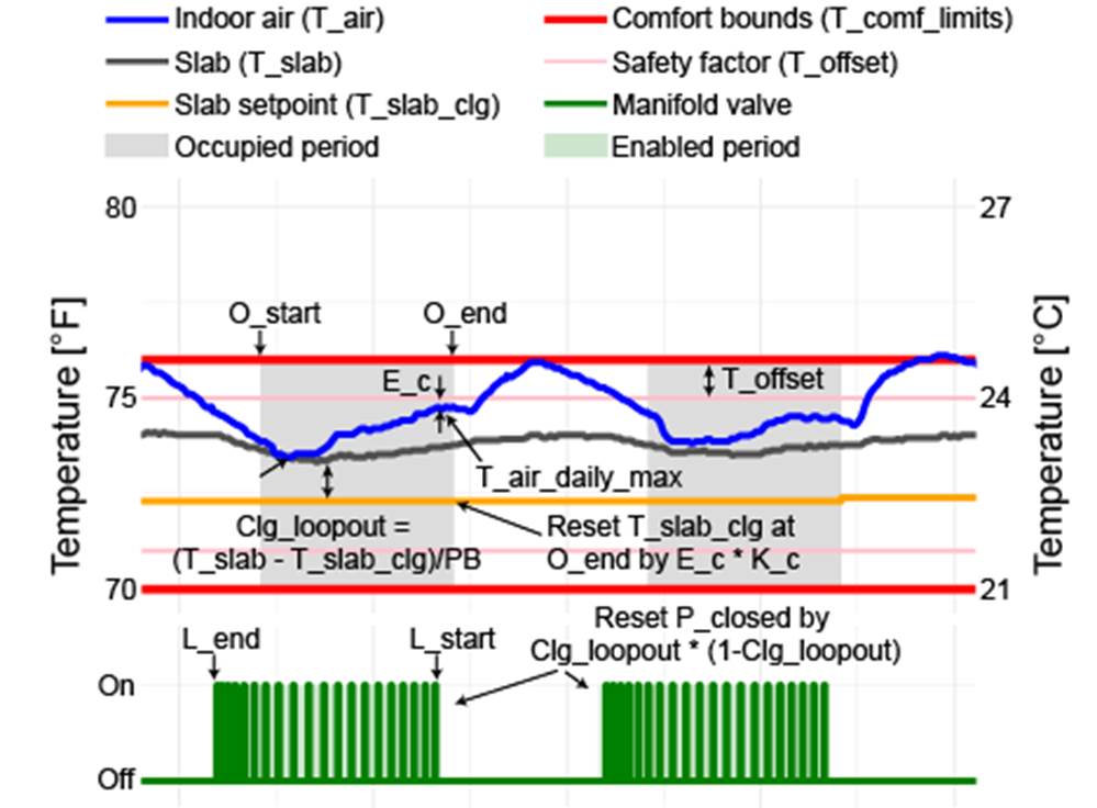
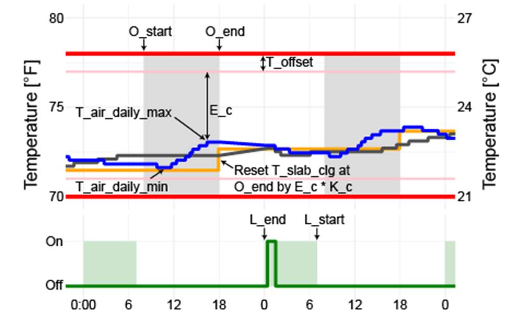
Figure 1: Visual representation of radiant sequences in cooling mode with Top) pulse width modulation (PWM) and Bottom) ON/OFF manifold valve control. Data is from the building automation systems of two different California large office buildings, not from simulation.